🚀 Elevate your Raspberry Pi Pico projects with pro-grade IO versatility!
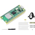
The KEYESTUDIO Raspberry Pi PICO IO Shield is a compact breakout board designed to expand the Raspberry Pi Pico's functionality. Featuring 26 GPIO pins, dual I2C, UART, and SPI communication ports, plus a flexible 6.5-12V power input, it enables seamless integration of multiple sensors and modules. Lightweight and easy to mount, this shield is ideal for professional-grade prototyping and development. (Raspberry Pi Pico not included.)
| RAM | LPDDR2 |
| Wireless Type | Bluetooth |
| Brand | KEYESTUDIO |
| Series | KS3017 |
| Operating System | MicroPython or Zephyr |
| Item Weight | 1.41 ounces |
| Product Dimensions | 3.29 x 1.78 x 3.29 inches |
| Item Dimensions LxWxH | 3.29 x 1.78 x 3.29 inches |
| Number of Processors | 1 |
| Manufacturer | keyes |
| ASIN | B0B45YWJH7 |
| Date First Available | June 15, 2022 |
R**E
Good
Fast delivery, good product.
T**C
Good development board
Good development board.I only wish it had a uSD slot or the pinout matched my uSD breakout boards.
S**N
Well made, I would buy again.
Exceeded expectations. Quick way to test a Raspberry Pi Pico - I would buy again.
J**D
Works Great!
Using with Raspberry Pi Pico with Header. Good quality. Perfect Breakout board.
L**U
Works as expected
This is really well designed for Raspberry Pi Pico. I really like the power input for external power which can be used to drive high current devices such as NeoPixel strips. I also like all pins are clear marked thus much better than a plain breadboard.
M**A
GPIOs headers are sequential but not in the same sequence as the Pins on the PICO module.
I like the fact that each PICO GPIO Pin on the male header has a 3.3v and ground pin right next to it.The GPIOs for key interfaces like the UARTS are also replicated along the bottom edge of the board.The main problem that i see in the design is this: while the GPIO pins are in strict numeric order on the Keystudio breakout, that is not how the PICO module pins are arranged; The PICO has a number of ground pins interspersed with the GPIOs.Why is that a problem? If you are working from a "Fritzing" diagram, the connections are shown in the same position as they appear on the PICO module and the diagrams do not label the signals being connected. So you can not visually duplicate the Fritzing connections on the Keystudio breakout without looking up the GPIO number the connection on the diagram represents. You could argue that the problem is with Fritzing not labelling the connections, but this is a reveiw of the Keystudio breakout. See Appendix A of the "Getting Started with Raspberry PI PICO" PDF for an example Fritzing diagram.Another peculiarity i noticed is this: if the PICO plugged into the breakout board is getting power from USB, the 5v header pins on the breakout are not powered. You must use an external DC source in order to have these 5v pins be live. That is suboptimal if you like to use USB for both power and stdio/serial.And one final thing. No schematic or notes are provided. It would be nice to know the exact details on the onboard power regulators and so on.
S**N
I’ve tried them all...
I’ve struggled to find a good breakout board for the Pico.This one is the best design so far.In general, your breakout board options are: screw terminals and/or 2.54mm spacing Dupont Connector compatible pins. The former are considered more flexible and secure, while the latter are considered more convenient.Why not screw terminals? Wires typically come in from the side and ideally need ferrules. So you need side clearance for wiring. And good luck finding tiny ferrules and crimping them on 28AWG wire. All of this just adds to the space needed by your enclosure.But many makers like screw terminals because they facilitate a more solid and lasting connection. One tip I can offer to nullify the screw terminal advantage is to not connect wires individually. Instead, always connect at least two wires in one Dupont female housing. Buy 1x4P and 1x6P female housing Dupont connectors. I guarantee you that 4-6 wires connected all at once and sharing one housing isn’t going anywhere; all the pin connectors reinforce each other. Another tip: you don’t have to use all the slots in the female housing. So if you need to attach wires but they’re not all next to each other, you can still use one connector for ALL your wires. A 3x6P connector, for example will handle data lines plus the power bus pins.Screw terminals or pins; either way, the main issue with the Pico is that it has exactly ONE 3.3V pin. That’s it! Everything you want to attach—your sensors, your screen, whatever—must share this single pin. The problem I have with other boards is that they don’t provide a power distribution bus to deal with this major limitation of the Pico. This board does.Some other boards do provide a power distribution bus, but then add LED indicators for every pin used. That’s great if you’re just messing around. But if you want to actually deploy something that runs off batteries, then you don’t want LEDs needlessly burning up energy for nothing. You won’t even see those LEDs once you put your project into an enclosure.One unhappy reviewer asks…"d) What's the 12v input power connector used for? Oh, no documentation. I don't know.”The answer to this is my next point. This board comes with a barrel connector that will power the Pico from any 6.5-12V power source. This functionality allows for a wide range of battery options. If, for example, you want to power your project with 1.5V AA batteries, you can use any number of them from 3-8. Or you could use a single 4.2V 18650 lithium. Or 2x18650s. Or you can ignore the barrel connector and just not use it. So many possibilities.Finally, the board has conveniently placed mounting holes. Other boards I’ve used have holes that are beneath the Pico. So to get access to them, the Pico (and anything attached) must be removed. The mounting holes are also very solid; on some boards, there is very little board material forming the holes and they’re quite fragile.Unfortunately, this board is not perfect. The aforementioned screw holes fit: nothing! M4 is too small; M5 is too big; #10 machine screws fit, but there’s no room for the screw heads. It would have been better (and cheaper) to use smaller M3 holes. Additionally, it would have been better to use a screw terminal in lieu of the barrel connector. Fortunately, the barrel connector isn't near any sensitive components, and can be removed and replaced. But adding a screw terminal will partially block a screw hole, which is my response to those who say, “Well if you don’t like the barrel connector, then just replace it”. Yes you can replace it (see image), but not without blocking a screw hole.
T**P
No documentation. DEBUG port useless. Not sure how to apply 5v input power
I'm new to this, so forgive me if I'm missing some basic understanding.a) The debug port pin connectors do not align even close to the debug pins on the Pico W. Pico W debug pins are near the middle of the Pico board while the Keystone debug pin connector is located at one end of the board. Therefore, you can't use the debug port on the IO Shield.b) No documentationc) Pin labeling for VBUS (Pico pin 40) appears to be labeled as VUSB. I don't know why. The Raspberry Pi Pico datasheet says power can be supplied from either the microUSB port or directly to the VBUS pin:"The simplest way to power Pico W is to plug in the micro-USB, which will power VSYS (and therefore the system) from the 5V USB VBUS voltage, via D1 (so VSYS becomes VBUS minus the Schottky diode drop).If the USB port is the only power source, VSYS and VBUS can be safely shorted together to eliminate the Schottky diode drop (which improves efficiency and reduces ripple on VSYS).If the USB port is not going to be used, it is safe to power Pico W by connecting VSYS to your preferred power source (in the range ~1.8V to 5.5V)."Since there's no documentation on the limitations of the IO Shield, I'm going to assume that the only way to power the Pico using the KEYESTUDIO IO Shield is via the micro-USB port.d) What's the 12v input power connector used for? Oh, no documentation. I don't know. The Pico W provides 3v power from the 5v input power, so not sure what 12v input power is for.I recommend getting something else.
Trustpilot
3 days ago
2 months ago